Case Study
SO-101 Handle Interface
A tool-free, magnetic handle interface for the leader arm of an open-source teleoperated robot.
Overview
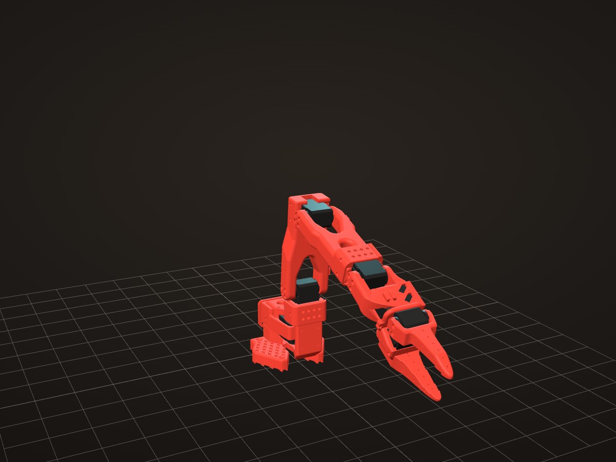
The SO-101 is an open-source robot arm pair from TheRobotStudio. You move the leader arm by hand, and the follower arm copies it. I assembled both arms as the team's mechanical engineer, and Ryan Porto wrote all of the control software.
My focus is the leader's handle: why the stock one is hard to use, and an interface that lets it be swapped without tools.
Problem
A Trigger Worked By The Thumb's Weakest Motion
The stock leader handle opens and closes the gripper with a trigger that the thumb pushes sideways. That motion is thumb abduction, the thumb's weakest direction. Bending the thumb, or pulling with the index finger, is far stronger. Both of us found the stock handle uncomfortable to use.
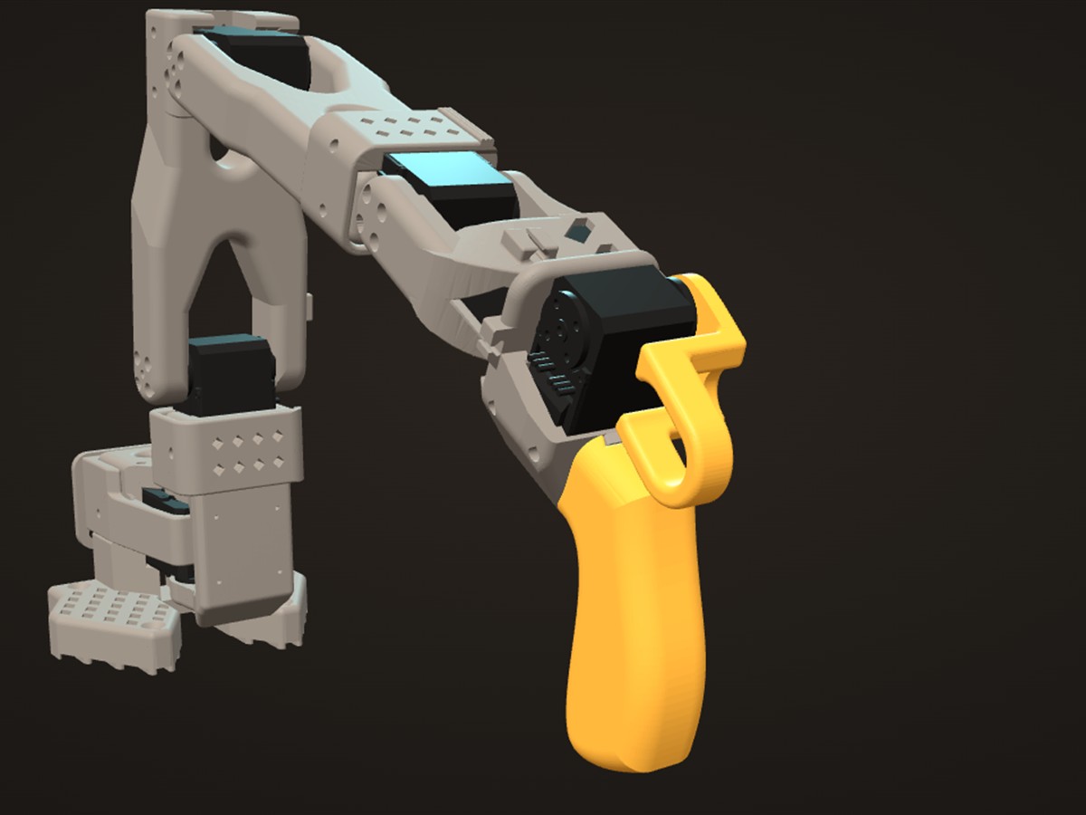
Before changing anything, I read the trigger's travel from the gripper servo through Ryan's software: 111°, from 124.5° to 235.8°. The software maps it 1:1 onto the follower's gripper, so that stroke is the gripper's whole working range and the baseline any new handle is measured against.
Requirements
What The New Handle Has To Do
- Move the pull to the index finger, in the hand's strong flexion direction.
- Come off and go back on without tools, so different handles can be tried on the same arm.
- Carry the trigger's torque into the servo without slipping.
Design
A Drafted Square Boss And A Magnet
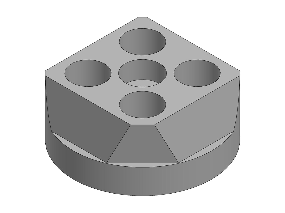
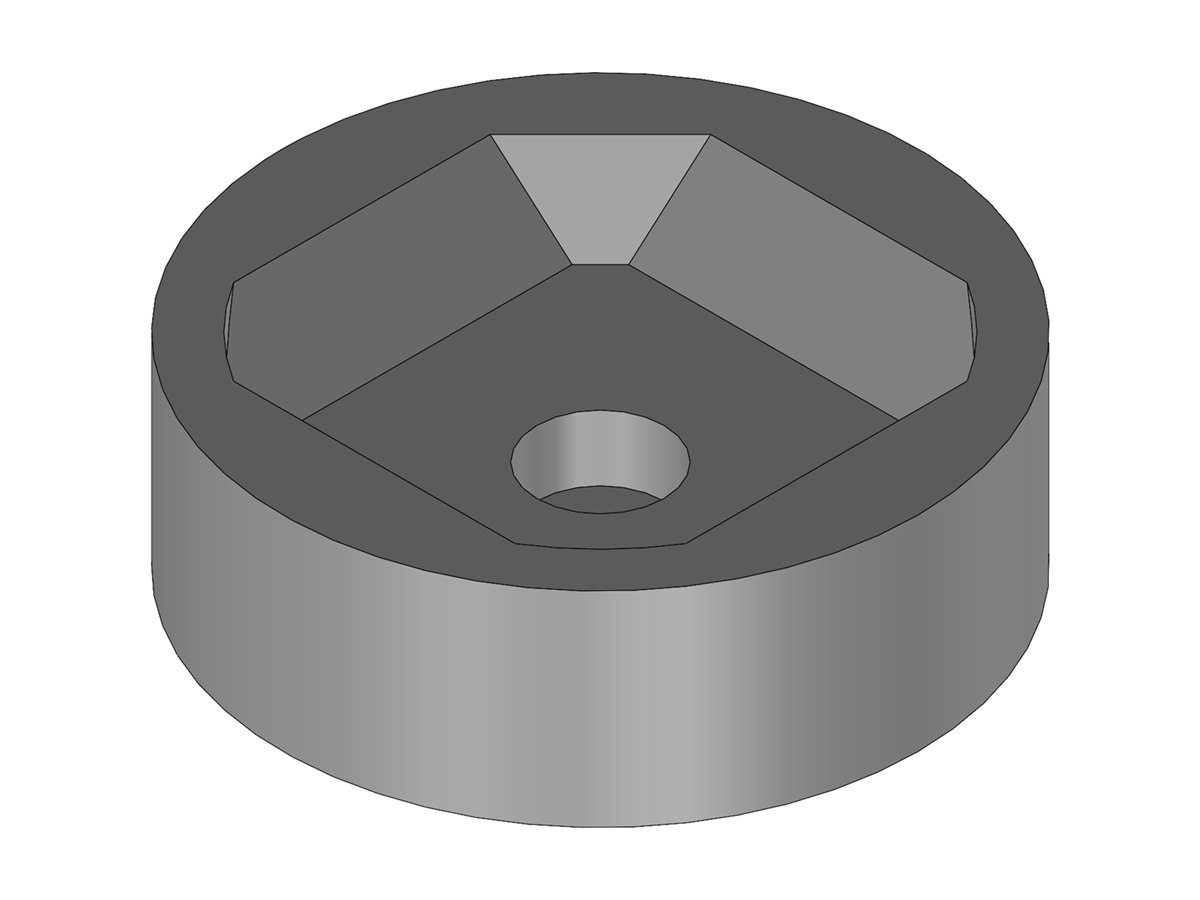
The interface is two printed parts. A hub bolts permanently to the gripper servo's horn with four M3 screws on a 14 mm bolt circle. A socket on the handle fits over it. Torque passes through a square boss with drafted flats, 18.4 mm across the flats at the top and 6 mm tall, with 20° of draft so the socket centers itself as it seats. A 6 × 3 mm magnet in each part holds the handle on. Pulling the handle off takes no tools.
I modeled every dimension of both parts in SolidWorks.
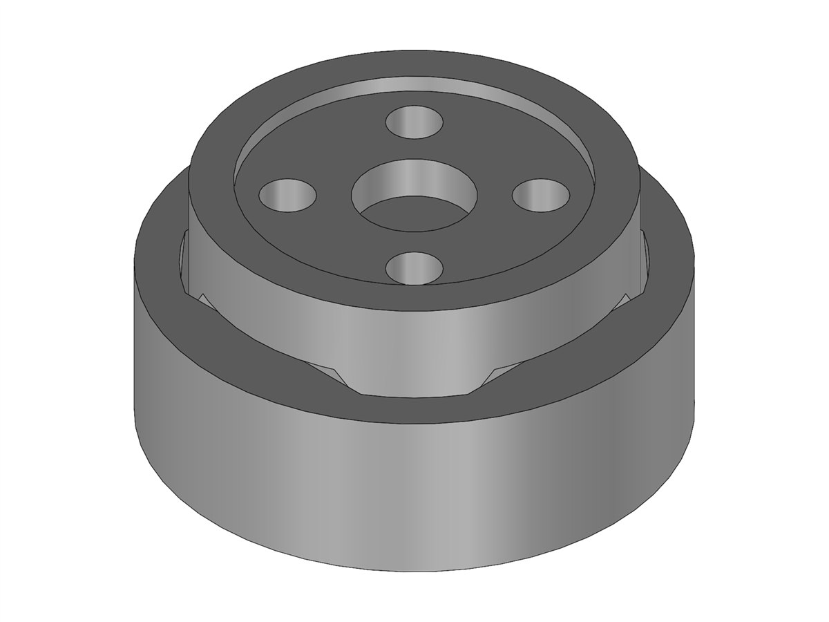
In CAD
Three Problems Caught Before Printing
- Bolt circle. My first hole pattern landed on a 12 mm bolt circle instead of 14 mm. I caught it by measuring the hole spacing in the model, 8.49 mm, against the horn.
- Mirrored index pad. The socket's alignment pad first landed in the mirrored corner, because the hub's index feature had been drawn in bottom view. The assembly's interference check caught it.
- An undefined dimension. The boss's base square had never been given a size. It sat at 22.8 mm, which with the 18.4 mm top and 6 mm height works out to 20.14°, not 20°. It is now fully defined from the draft angle. I chose to hold the top size constant, because the thinnest wall, 1.27 mm between a counterbore and a flat, is at the top.
Status
Where It Stands
The first print of the interface seats as designed and holds magnetically.
Next Steps
- A draft-angle test with matching hub and socket coupons at 0°, 15°, 20° and 25°, to find where the drafted flats stop holding without the magnet.
- Measure the fit gaps on the printed parts.
- Design and print the index-finger trigger on the new interface.